Resonant Converter for Fluorescent Lamp Drive
Power Electronics
Background and Design Approach
Fluorescent lamps require above 300 V to strike by ionizing mercury gas, which then emits UV light to cause phosphor to fluoresce. If the striking voltage is below the threshold, the lamp cannot properly light up. Therefore, a high strike voltage is critical to both safe and successful operations. When the lamp strikes, the negative resistance of the lamp requires a lower voltage to drive sufficient currents into the lamp.
The design requirements for the resonant converter are as follows:
- Input: 30 V (specification given by lab setup)
- Output:
- 400 V when lamp is in the off state (Rlamp = ∞)
- 50 V when the lamp is in the on-state (Rlamp ≈ 52 Ω)
The main design decision lies within the sizing of the L, C components to achieve the appropriate gain at resonant frequency when the circuit is unloaded and loaded. The key considerations for L, C selection can be summarized as:
- Gain at resonant frequency for state-dependent resistance of the fluorescent lamp
- Inductor core saturation (which leads to reduced inductance as calculated from turn ratio)
- Core losses
- Inductor and capacitor ESR (which dampens the gain)
Design Decisions
The lab inventory only has a few capacitors rated at high voltage (400V). Therefore, I anchored my calculations based on these available parts and measured their ESRs with an LCR meter for transfer function computation.
To compute the gain of the resonant converter, I used fundamental harmonic analysis (FHA) to approximate the Fourier series of the input square wave as a fundamental harmonic. The square wave switches between 0 V and 30 V and therefore has both a DC offset of 15 V and a periodic waveform, which can be simplified into its fundamental harmonic using a Fourier decomposition:
\[\frac{2}{\pi} \cdot 30 \cdot \sin(\omega t)\]
This analysis is valid given that the LC-network's resonance is tuned to be very close to the switching frequency.
The net gain of the system is therefore given by:
\[\frac{V_{out}}{V_{in}}\bigg|_{\text{lamp off}} = \frac{2}{\pi} \cdot \frac{j\omega R_c C + 1}{1 - \omega^2 LC + j\omega C(R_c + R_L)}\]
\[\frac{V_{out}}{V_{in}}\bigg|_{\text{lamp on}} = \frac{2}{\pi} \cdot \frac{1}{1 + \left(\frac{1}{R} + \frac{j\omega C}{j\omega R_c C + 1}\right)(j\omega L + R_L)}\]
An optimization sweep was conducted on a range of inductor values with an estimated ESR of 1Ω to achieve an output of ~400 V and ~50 V when the lamp is in the off- and on-state, respectively.
To achieve the selected inductance, core losses and inductance variation due to core saturation must be considered. Both ferrite and powered iron cores are available in lab inventory, and a comparison of their estimated losses using the computed magnetic field from the output current indicates that powered iron has about ten-fold more losses. As such, a ferrite core is used for this design, and the inductance is sized slightly higher than the value derived from the transfer function to mitigate the downsizing due to core saturation.
Build Results
A totem pole switches the 30 V DC supply, and the lamp was illuminated successfully! The output waveform is measured using a voltage divider across the output (Vscope = 0.03 · Vlamp).
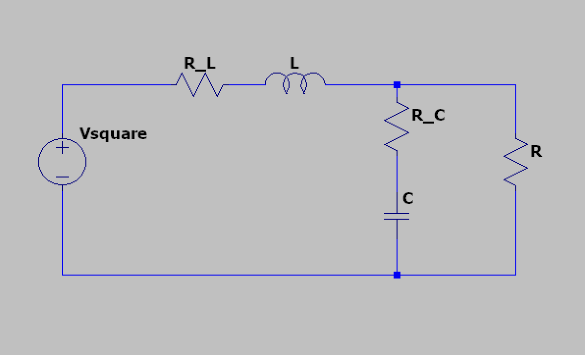
The output waveforms shown below before, during, and after strike events demonstrate the different states of the mercury gas:
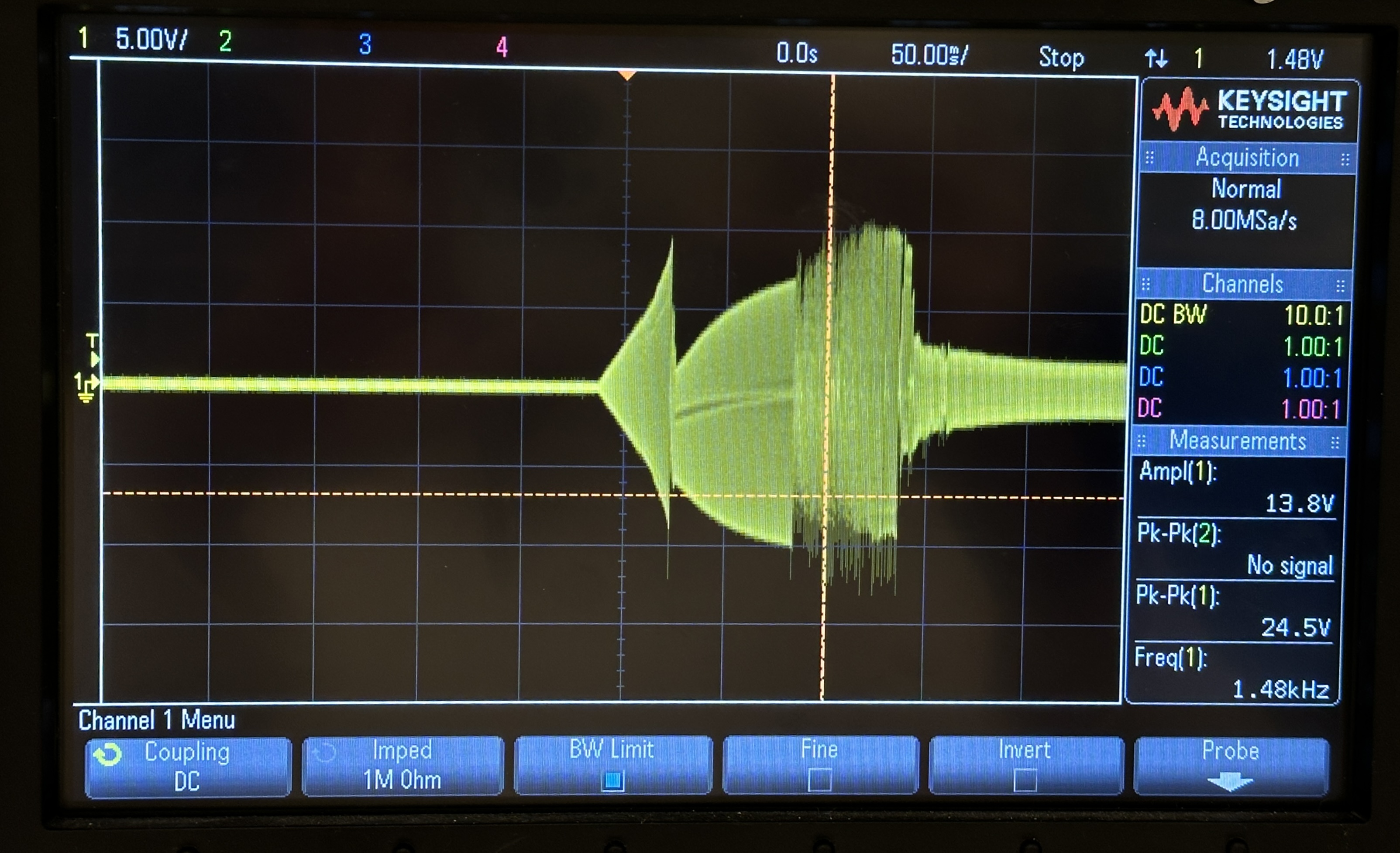
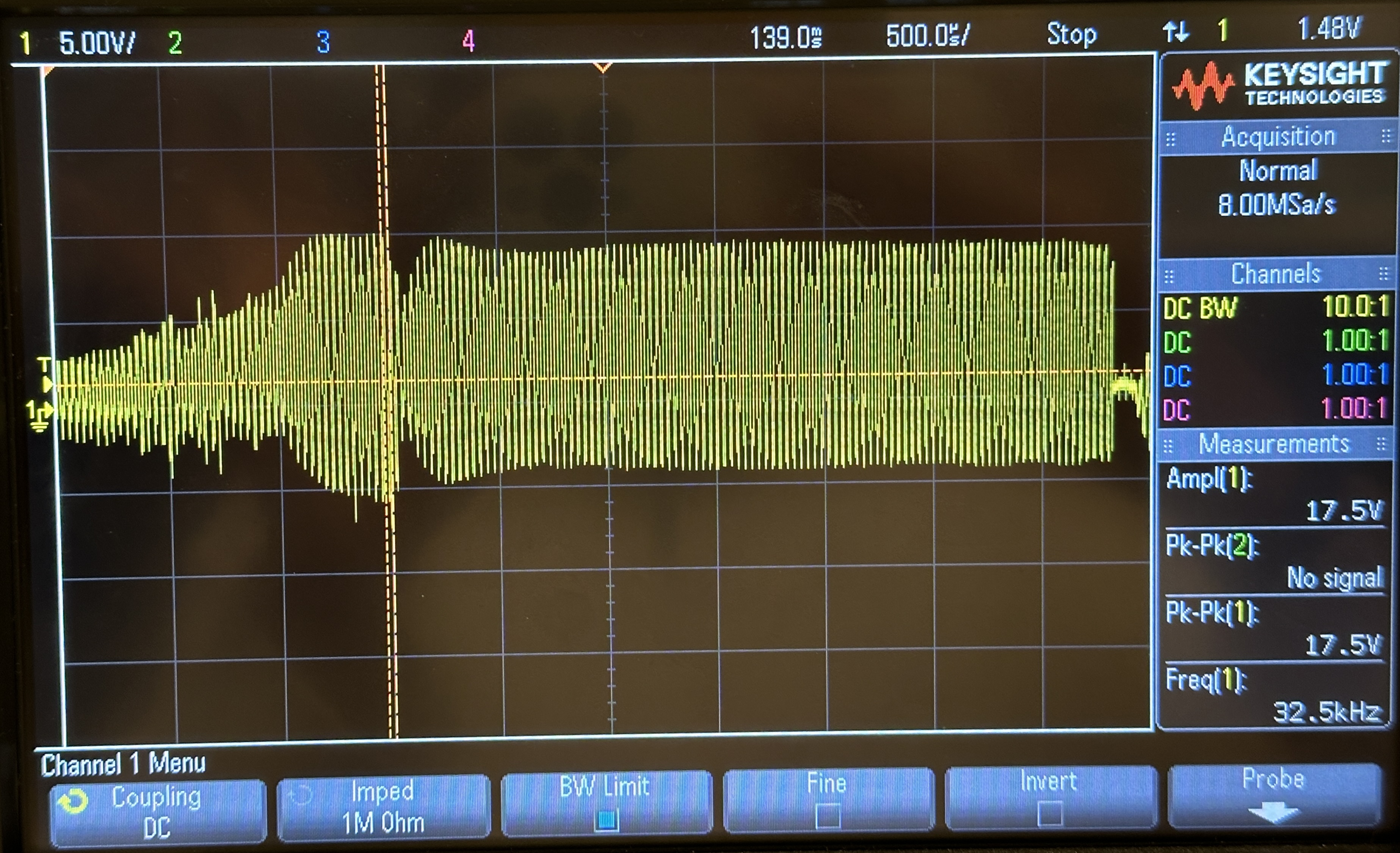
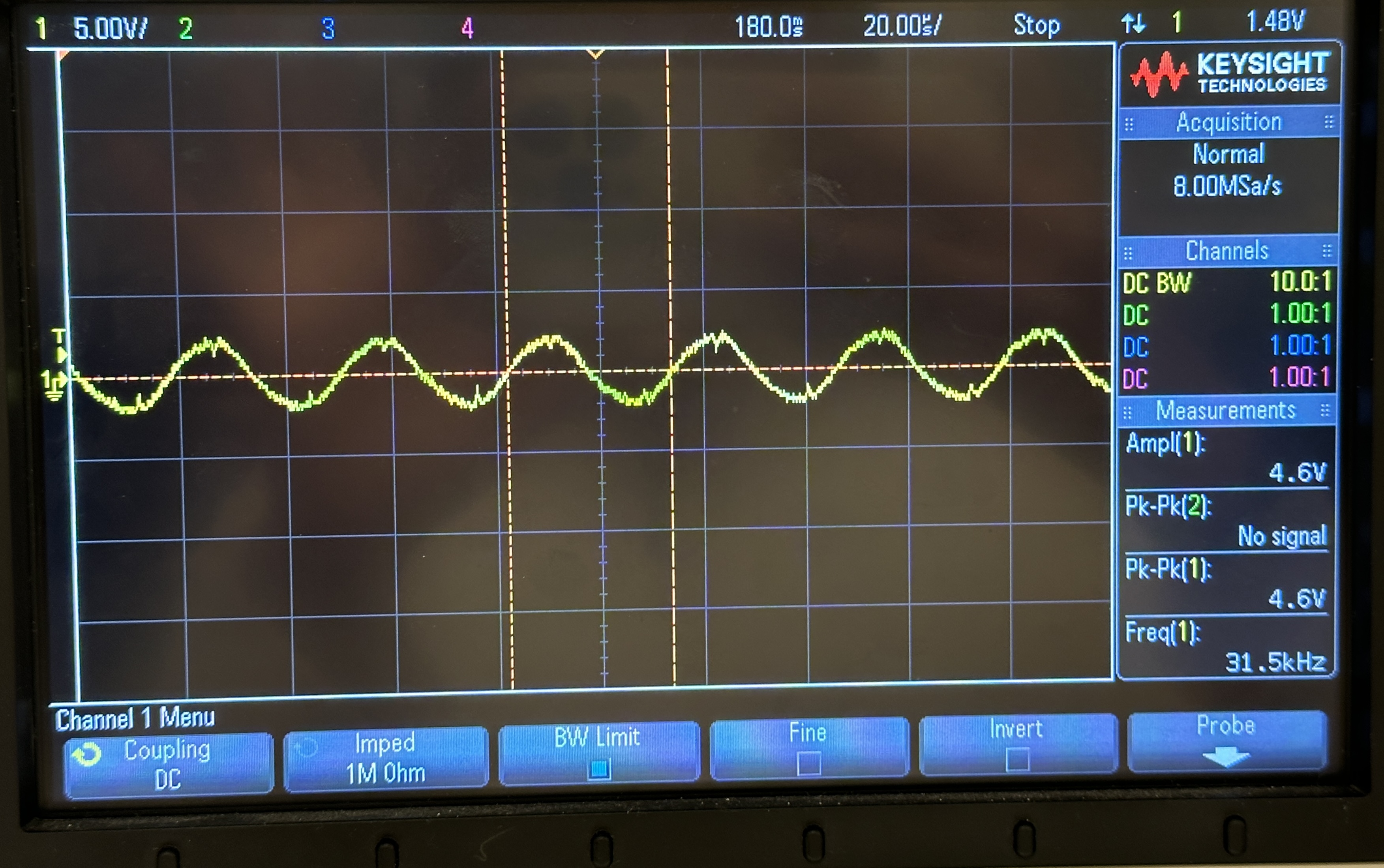
The striking and steady-state waveform has an amplitude of around 10 V and 2.8 V, respectively, indicating a 333 V strike and 100 V steady-state voltage.
Reflections
This topology is a canonical, simple resonant converter that requires analysis primarily in the frequency domain, similar to a buck converter. The time-invariance of the circuit and approximations I was able to use simplifies the analysis compared to other switched-mode converters.
Despite its simplicity, it is a fundamental model of inverters that demonstrates relevance in a wide range of applications that demand an AC power source, such as induction heating, plasma generation, and wireless power transfer.
In fact, I am exploring a topology related to this model in my research, which has currently undisclosed details, but we are optimizing a class E inverter for high frequency applications..